Sunday 26 November 2017

Tag Level Parameter

If you ever need to add a Level parameter to you tag, when you place your label you will notice that most of the Categories won’t have the Level Parameter in the ‘Select available fields from:’ list.

So you have to apply a little work around to gain access to this field.


  • Firstly change the Category of the Tag to a ‘Ceiling Tag’. 
  • Place a Label on the screen and select the Level parameter from the fields. 
  • This will create a Level Parameter Label. 
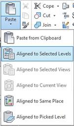
  • Select the Label on the screen and ‘Cut to Clipboard’. 
  • Now you can change the Category of the Tag Family to the one you require. 
  • Paste the Label back into the Tag family and you now have a Label reporting the Level parameter.

Thursday 26 October 2017

Formula Greater Than or Equal To

If you have a situation where you would like to control a parameter determined on whether another parameter is Greater Than or Equal to a third parameter. You might think that the formula should read….

Parameter A = Parameter B >= Parameter C

The only problem is that Revit won’t allow you to insert the condition >= in the Formula, and will return an error.


So if we think in reverse and work with a ‘not’ statement we can use Parameter B < Parameter C.

So the formula will read….

Parameter A = not(Parameter B < Parameter C)


Sometimes you have to think a little out of the box to bend Revit to your will!

Monday 2 October 2017

Paste to Selected Levels

If you have a selection set you would like to copy to multiple levels in your project model, you can quickly and easily complete this process by using the Paste  ►Select Levels tool.

Firstly select the Elements you would like to copy.

Then using the Copy to Clipboard Tool in the ribbon above, or using the ‘Ctrl’ + ‘C’ on the keyboard.


Now click the ‘Paste’ drop down arrow, to bring up the extra ‘Paste’ options.

Click the ‘Aligned to Selected Levels’.


This will bring up the ‘Select Levels’ dialogue box where you can select the levels to paste the elements. You can select multiple Levels by holding down the ‘Ctrl’ or ‘Shift’ Keys. Once selected click the ‘OK’.


Sunday 13 August 2017

Family Creation Process

When creating families for your project here are some basic best practices to keep you family running smooth and trouble free.

  1. Plan your family before you begin creating, this will allow you to make informed decisions during the creation process. Try to keep it simple for others to use and edit.
  2. Select the correct Family Template file to start. 
  3. Define Category and additional Sub-categories. 
  4. Create a skeleton of Reference Planes. 
  5. Dimension and create appropriate Parameters and apply to Reference Planes, (remember to utilise Shared Parameters where required). You should also create your Parameters in the appropriate ‘Group Parameter Under:’ section, this will help users find your parameters quickly. Don’t put everything under ‘Other’. 
  6. Test your Parameters, flexing your model and ensuring you don’t get any errors. (You can create additional ‘Family Types’ of you family, this will help testing as you can switch between Types rather than having to alter values all the time.) 
  7. Create 3D and 2D elements and lock them to the Reference Planes where required. This process may include the addition of nested families. 
  8. Apply Visibility Settings to control individual element visibility. 
  9. Test your Parameters again. 
  10. Save you Family, in the correct location and Name it in accordance with the your offices' Naming Conventions. Remember the model is going to be sent out of the office, People outside of your company are going to need to find and analyse these families. 
  11. Test the Family in a Project environment. Open a new project and test the family before you load it into your actual project model.


Although there are many variations of Family creation, if you follow these simple steps no matter how complicated your Family is it will have the best chance of working first time, every time.

The common thread through this outline is to test and test often.

Sunday 16 July 2017

Browser Organisation

A really quick way to change you Project Browser Organisation without having to go to the View Ribbon and then into the User Interface tool, is to highlight the ‘Views (all)’ heading at the top of your Project Browser and then in the Type Selector in the Properties dialogue box, select the Browser Organisation you would like to apply.


This process also works for the Sheets Browser Organisation.

Sunday 18 June 2017

Worksharing

When you are working on a workshared project file it is always a good idea to keep an eye on the Active Workset. Whatever the Active Workset is set to, this is the Workset all of your new modelling will be created under.

You can find the Active Workset in 3 locations.

In the Collaborate Ribbon, In the Worksets dialogue box, or the most convenient which is located at the bottom of your modelling area.


The Active Workset can change without you realising, resulting in your work being located on the incorrect Workset. This is because different users change the Current Active Workset in their local file. When they synchronise it will make their Active Workset as the default Active Workset next time you open the Central File.

The Moral of this story is to keep an eye on the Active Workset, when you next open (or create) your Local file.

Wednesday 31 May 2017

Dynamo - Twisting Tower

Whilst I primarily use Dynamo for BIM Management tasks, I do like to delve into the Computational Modelling for facade optioning and building forms.

I am constantly getting asked about.... How do I create one of those twisting towers?


So I decided to put up a small tutorial and the Dynamo script for anybody interested in creating a twisting tower.

Starting with a Mass family, I create a rectangular shape on the Ref Level and a point element to act as my rotation point.


From there Dynamo takes over with inputs for "Number of Levels", "Floor Height", "Bottom Floor Rotation" and "Top Floor Rotation"

Just select the Rectangle and the point and twist away.....enjoy.....


You can take this much further by adding floors and facade elements, but playing with the form is so much fun!!!

Twisting Tower Script

Turning Off Everything

If you need to turn off all of the Model Categories, Annotation Categories, Analytical Categories or the Imported Categories in your model view, there is a really fast way without having to select Categories individually.

(This process can be very useful to determine what is modeled and what is annotation in the view.)

If you open the Visibility/Graphics Overrides dialogue box. In the top left corner of each Category Tab, there is a tick box ‘Show model categories in this view’. If you untick this box it will hide everything listed below in that tab. (For this example I was using the Model Categories tab, the other tabs tick boxes are named accordingly)


Alternatively for model elements you can use a parameter in the View properties dialog box, that will allow you to change Model Display from "Normal" to "Do Not Display"

You also have an option to "Halftone" model elements.


Friday 5 May 2017

Selection Filter Alternative

When you have multiple elements from multiple categories selected in your model, an even quicker way to filter your selection is to select the pull-down menu just below the Type Selector. This will show the categories that have been selected and you can pick the category to filter.

This filter should be primarily used for smaller selections in your model.

It doesn’t work like the traditional filter, but it allows you to filter to a Category and alter the Parameters only. If you try to move or copy it will alter everything initially selected.


Another limitation to this filter selection, is that you can only select one category to filter.


Tuesday 18 April 2017

Brisbane Computational Design Group April Meeting


I am co-chairing the Brisbane Computational Design Group. Meeting are on the first Wedesday of each month (apart from April when it will be held on the Wednesday the 19th)
6pm to 8pm
Agenda and Venue to be confirmed prior.


Twitter: @compDesGrp
Slack: brisbanecdg.slack.com

Thursday 16 March 2017

Parameter Type/Instance Switching

When you have multiple dimensional parameters in your Revit family, a quick way of switching between a ‘Type’ and ‘Instance’ parameter is to select the dimensioned parameter, and in the options bar you can select (tick or untick) the Instance Parameter option.

This will change it between a ‘Type’ and ‘Instance’ parameter without having to go into the ‘Family Types’ dialogue box.


Note: This only works on visible parameters (ones you can select). All the others you will still have to go to the ‘Family Types’ dialogue box. 

Sunday 5 March 2017

Line Length

If you select a line in your model and look in the instance properties dialogue box you will see that it will display a ‘Length’ parameter value, giving you the length of the individual line. If you are lucky enough it will also display a temporary dimension showing the length.


If you would like to determine the total length of multiple lines joined together (Chain of lines), this can only be achieved with Model lines.

Under the Modify Ribbon select the ‘Measure Along an Element’ tool and then select the chain of lines. This will display the ‘Total Length’ in the Options Bar.


If you would like to determine the length of multiple Detail lines, simply select the chain of Detail lines and use the ‘Convert Lines’ tool in the ribbon above. This will convert the line work to Model lines, now you can utilise the ‘Measure Along and Element’ tool. Once the ‘Total Length’ has been determined, just convert them back to Detail lines using the same ‘Convert Lines’ tool.


Sunday 26 February 2017

Double Clicks

If you ever wanted to define how Revit elements react to a mouse Double-click.


If you go to the Revit Application Button ►Options ►User Interface ►Double-click Options and select the Customize button, you will be able to adjust how Revit reacts when you double click elements.


Another nice Double-click tip is when you Double-click the middle mouse button (scroll wheel) it will Zoom to Fit.


Sunday 5 February 2017

Visibility Graphics and Linked Files

When you link Revit models into your project, Revit allows you to control their visibility graphics in your host file. This can be controlled many ways….

By Host View – Visibility graphics is controlled by the host view.
By Linked View – You can use a view in the linked file to set the visibility.
Custom – You can independently control the visibility of the linked file.

When you select on the Revit Links Tab in the Visibility Graphics dialogue box, it will list all of the Revit links being used in the current project. If you expand the Revit Link, you will notice that there is a sub-category to the Revit link. This is the individual instance of the linked file and it can be controlled individually.

Changing from ‘Not Overridden’ can cause major headaches in your project file if you start manipulating the instance (sub-category) display settings unnecessarily, it makes visibility settings hard to find in views. Normally there is no need to adjust the visibility of the instance of the linked file, especially if there is only one instance (sub-category).


Please leave this as ‘Not Overridden’!


Use the main category of the linked file to control the visibility.

The only time you need to adjust this setting is if you have multiple instances of the linked file in your project that need to have their visibility controlled individually.

Sunday 29 January 2017

Wall Intersections, Structure and Partitions

When modelling in Revit the program defaults to joining walls when they intersect. When you model contains both structural walls and internal partitions the default doesn’t give you the correct intersection both physically and graphically. This is a situation where the walls should have the ‘Disallow Join’ function applied.

In the example below I have a partition wall intersecting with a structural wall. You will notice that the intersecting line weight does not show the structural wall continuous and the end of the partition extends into the middle of the structural wall.


If you right click on the dot at the end of the wall and ‘Disallow Join’, this will break the attachment of the 2 walls.


The end of the partition can now be dragged back to the intersection with the structural wall. 


The intersection of the walls is now correct.

I know that there are a few extra steps, but this will give you the outcome required to represent the model correctly in your documentation and also when it is exported for use throughout the Project Team.

Sunday 22 January 2017

Linked Levels and Grids

When you have linked Revit models loaded into you project file, the positioning is usually controlled by the shared coordinates system which makes the Grids and Levels of the linked file kind of redundant. This doesn’t stop them showing up in all of your Plan, Elevation and Section views of the host file.

A way of globally turning the Grids and Levels off in the linked model is to go to the Manage Links Dialogue box.

Highlight the linked project and select the Manage Worksets button.


This will open up the Manage Worksets Dialogue box for the linked file.

You can close the Workset for ‘Shared Levels and Grids’ by selecting the Workset and selecting the Close button.


If you ever need to check the linked files Grids and Levels, the Workset can still be opened through Manage Links.